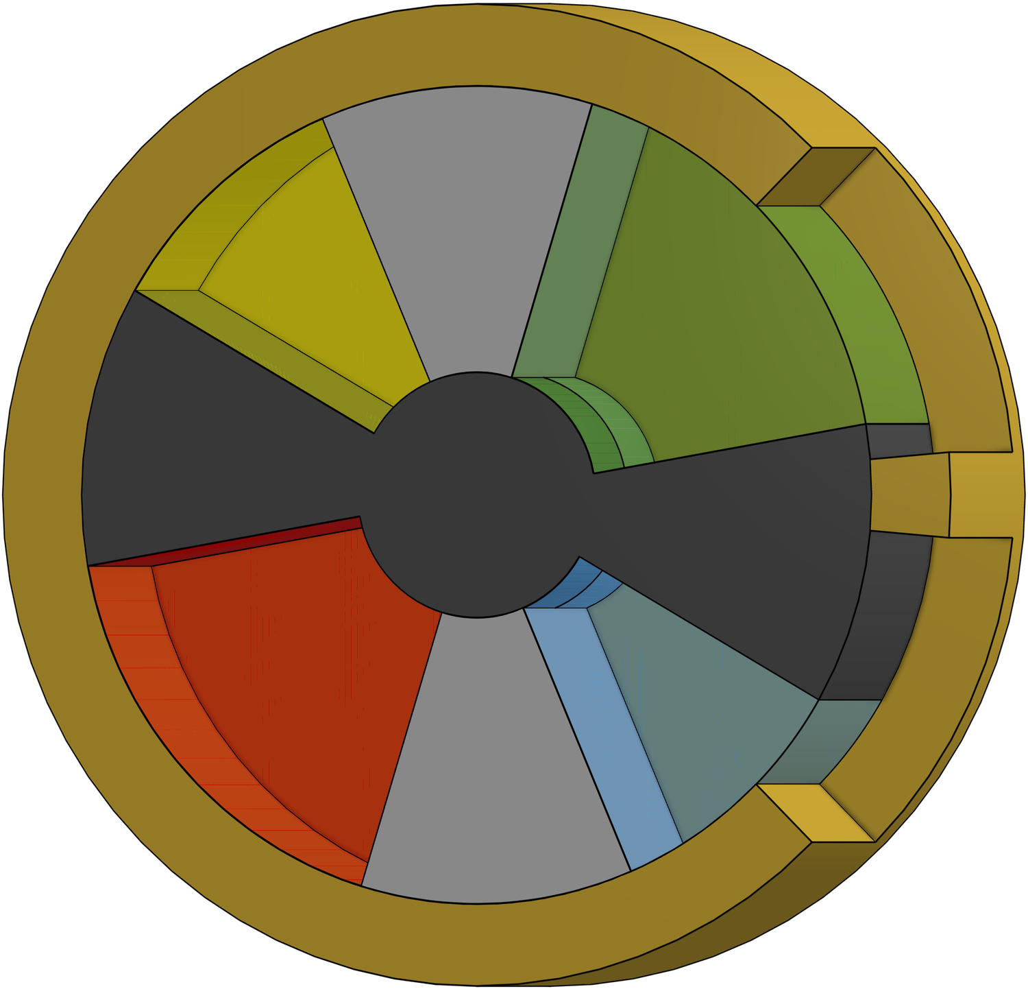
In this post we discuss what CAES is, why any one cares, what it has to do with Galin engine, and finally opinionate about its future.
Compressed Air Energy Storage (CAES) is a type of battery which holds energy in the form of compressed air. Caveats to the following discussion:
I am not an expert in thermodynamics, hence, there will be a lot of exploration here of basics.
CAES is an interesting option for storing energy, it certainly has the attractive feature that one is dealing with plain, old, ordinary air which is easy to get, not flammable, not toxic. The concept of CAES has been discussed since the 1940s, with two plants in current operation. Recently, there seems to be a general revival in interest in CAES systems - with a lot of attention paid to the storage process of compressed air, i.e. is it diabatic (heat due to compression lost to environment) adiabatic (heat somehow stored, maybe in an external reservoir) and even isothermal (heat not generated due to compression - am interested to know how “slowly” compression/expansion needs to occur for this condition to be met).
With renewable energy sources becoming more and more available, their main drawback is coming to the front, which is their intermittent nature. Energy storage (specifically storing the electricity generated by renewable systems) is a necessary component for the future if we are to attempt to move to a renewable grid. CAES systems are one such option, with excess electricity being used to drive a compressor which pushes compressed air into a storage reservoir, and then at times of demand (and no renewable supply) the compressed air discharged through an expander to generate electricity.
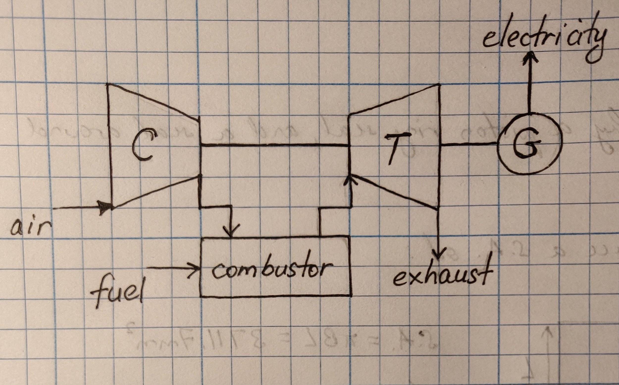
The concept of CAES is historically based on the gas turbine cycle, see figure 1a, where electricity is generated by compressing air, igniting fuel and driving the mixture through a turbine to generate electricity. The difference in CAES systems (figure 1b) is that there is an arbitrary time delay between compression of air, and generation of electricity facilitated by storage of compressed air. If we are after a renewable grid, then turbine cycle CAES systems are a bit of a problem as they still produce CO2 due to combustion of fuel to return some heat to the compressed air. So, let us simplify CAES systems further and just have a compressor/expander mechanisms either side of the compressed air storage.
Let us compare these numbers (figure 2) with the energy density of petrol (gasoline) and lithium-ion batteries to give us some context for these numbers; the energy density of petrol and lithium-ion batteries are \(34 GJ/m^3\) and \(1.4GJ/m^3\) respectively, compared with \(200 MJ / m^3\) for compressed air at a stupendous compression from 1 atm to 400 atm. These numbers show that the energy density of petrol is at least 170 times greater. But, this comparison is not entirely fair as the energy that is extractable from petrol is only about 20 - 40% (with current gensets) so, in practice, petrol is actually about 34 - 68 times higher. But…this comparison is still not fair as we are comparing a perfectly reversible isothermal process.
Figure 1a - the gas turbine cycle schematic for generating electricity
Figure 2 - energy density of compressed air in isothermal compression. Efficiency is assumed to be 100%.
What I find lacking in the articles and descriptions of various CAES systems are basic parameters that would allow one to understand the efficiency of the system. Efficiency is a bit of a loaded term, what do we mean? Nothing fancy; not isentropic, adiabatic, constant enthalpy efficiency….. or other fancy terms due to various assumptions. Let’s keep it simple. In this post we consider efficiency as the ratio of energy between input and output - E_in is the electrical energy that is input into the system, and E_out is the electrical energy delivered by the system. In this post, let us look at the energy density of a simple CAES system, i.e. one in which compressors are 100% efficient, expanders/generators are 100% efficient.
Let us start by calculating the energy density of a CAES which is able to achieve isothermal compression (i.e. a compression/expansion slow enough to achieve zero heat exchange with the environment): $$W_{A->B}=p_BV_Bln\frac{p_A}{p_B}+(p_B-p_A)V_B$$
Figure 2 plots the energy density as a function of the pressure ratio (output pressure/input pressure).
In actual fact, we are usually dealing with polytropic compression, which loses a lot of the compression energy to heat. Let us calculate what the ideal polytropic compression will give us in terms of energy density. The work done during polytropic compression of gas is given by:
$$W_{A->B}=\frac{p_AV_A}{n-1}(1-c^{(n-1)})$$
where \(n\) is the polytropic index (about 1.4 for air) and \(c\) is the compression ratio given by \(e^{ln\left( (\frac{p_B}{p_A})/n \right)}\). Figure 3 plots the energy density as a function of pressure ratios, and figure 4 plots the percentage of work that is converted directly to a temperature increase of the compressed gas above ambient (assumed to be about 295K).
Figure 3 - energy density of compressed air in polytropic compression process. Efficiency assumed to be 100%.
Figure 3 shows that at 400 atm we get around \(81MJ/m^3\), which is 2.5 times lower than isothermal density, but, we are assuming that we are able to somehow conserve all that heat (81%, see figure 4) and add it back during expansion. Storage of heat, I believe is quite difficult. If you’ve converted your energy to heat “for use later” I feel like you’ve already lost the entropy game. So let us take a look at what energy density will be if all heat energy is lost to the environment (diabatic process); figure 5 plots this case.
Figure 5 - energy density of compressed air in diabatic compression process. Efficiency assumed to be 100%.
Figure 1b - the CAES system schematic, similar to the gas turbine cycle, but with a reservoir in place for storing compressed air.
Figure 4 - percentage of compression work/energy converted to thermal heating of compressed air.
Figure 5 plots the worst case, when we lose all the heat generated during compression. We get an energy density of \(15 MJ / m^3\) or 5 times lower. In actual fact, with advances in heat storage etc, we will probably achieve something between \(15 MJ / m^3\) and \(80 MJ / m^3\). BUT, that’s not taking into account losses of the system due to inefficiencies in the compressor, and expander/generator. Let us assume compressor/expander efficiencies of 70%, i.e. we get: \(7.4\) to \(40 MJ / m^3\). This translates to \(2 kWh / m^3\) to \(11 kWh / m^3\).
So, let us say we want to compress a shipping container full of air (a large shipping container has about \(76 m^3\) capacity). Using the above numbers, a shipping container can store between 152 kWh and 836 kWh. But it will take some time to fill it up. The flow rate of the compressor is important, say 320 L / min (this is a value of the inflow). So we need to understand that in our example (400 atm compression) we compress the volume of the air by about 72 times, and hence we would need to suck in 76 x 72 x 1000 L of air. We calculate that it will take us (76 x 72 x 1000 / 320 = 17100 min) 285 hrs, 12 days, to fill up the shipping container with 152 kWh to 836 kWh of energy.
We can also do this calculation backwards, to calculate the rate of charging possible in this idealised CAES system. At 320 L / min the compressor actually generates 4.4 compressed litres per minute (320 / 72). From our calculations above, every litre contains between 0.015 MJ and 0.08 MJ of energy, hence the max rate of energy absorption of our compressor is: 0.067 MJ to 0.36 MJ every minute. The compressor cannot process more energy than this per minute. The power rating of our CAES system on the input side is: 1.1 kW to 6 kW.
Let us also by extension assume that the compressor works equally well as an expander, this means that its outflow is bounded at 4.4 L / min. So, on the output side, our CAES battery, the size of a large shipping container, is actually a 9 W to W battery with a storage capacity of 152 kWh to 836 kWh. What does this mean? It means that our idealised CAES battery cannot directly power any equipment that requires above 6 kW. This kind of means that we have a massive battery, but very weak input output wires, and a potentially massive internal resistance (to account for the heat loss during compression).
Now, this does not HAVE to be the case. In fact, most systems use turbines to generate energy on the output, which are probably (yeah?) higher flow devices thereby increasing the discharge rate of the CAES battery.
Where does Galin engine fit into all of this?
Well, most compressor/expander systems in use by CAES systems are your vanilla reciprocating piston compressors. Reciprocating piston pumps are able to perform 1 compression cycle per shaft revolution. A compressor based on the Galin architecture, for the same cylinder volume, performs 8 compression cycles per shaft revolution, hence the flow rate is much greater, hence, we’d have to wait a lot less to charge and discharge our battery. Additionally, a Galin expander is just the Galin compressor with the shaft running in the opposite direction, therefore the same unit can be used for both. There is no need to have separate compressor and turbine components. And finally, electrical machines like the cold, the copper losses decrease and the regeneration efficiency on the expander side will increase.
Pontifications:
Lots of wins for using the Galin architecture for CAES systems. But the above analysis certainly still leaves lots of room for pause - why bother? Doing so much work, and having so little to show for it.
Most of the energy storage in the world is in pumped hydro. It is difficult to obtain energy storage numbers, for some reason (possibly because of the ability for direct comparison to power generation) capacity is reported as GW, not GWh. (That’s like comparing buckets, but one person is talking about the hole in their bucket, and the other person is talking about the size of their bucket.) Here however, we finally learn that pumped hydro capacity is around 8500 GWh @ 160 GW discharge capability. The energy density of pumped hydro is around 0.2 - 2 Wh/L (that’s theoretical, and so must be discounted by pump/turbine inefficiencies, and maybe even loss of water due to evaporation?).
Note, even in the worst case scenario where all the heat of compression is lost to the atmosphere, CAES is at least 10 times more efficient than pumped hydro. However, pumped hydro is the dominating method of storage. Why?
Because there is no heating necessary of the system during the storage/discharge processes?
Heat is very difficult to contain/store and control.
Water flow (which determines the power delivery capacity of pumped hydro) is limited only by the width of the channel between up and down tanks. Power delivery of CAES systems is low.
References:
GitHub repo: https://github.com/ngalin/caes
Articles/papers:
https://www.mdpi.com/2673-7264/3/1/8
https://www.humsterlandenergie.nl/resources/LInks-duurzaam/Linkpagina/Efficiency-of-Cormpresse-Air-Energy-Storage-Elmegraard---Brian---Brix--Wiebke-2020.pdf
https://www.sciencedirect.com/science/article/pii/S277268352200022X
https://www.mbie.govt.nz/building-and-energy/energy-and-natural-resources/low-emissions-economy/nz-battery/
https://www.wsp.com/en-nz/news/2022/wsp-secures-contract-for-alternative-energy-storage-study
https://www.alfalaval.co.nz/industries/energy-and-utilities/sustainablesolutions/sustainable-solutions/clean-energy/energy-storage/
https://www.nzherald.co.nz/business/compressed-air-comes-to-fore-as-method-of-storing-wind-solar-energy/3IHBI2OHDQZZLGO7TBXDJTV5TA/
https://www.sciencedirect.com/science/article/abs/pii/S0306261916302641


