We have previously described the Galin Pump (here). In this post we will be discussing (in real-time, as of 22nd Jan, 2024) how our 3D printing development of a prototype is going.
First, let us start with a video (first prototype videos, just like UFO videos, are always inadequate and fuzzy) demonstration (made 19th Jan, 2024) of the pump running pumping water:
Overall, we are aiming to demonstrate salient features of Galin Technology with our pump prototype, these are:
high flow (relative to a similarly sized piston pump)
software controlled flow adjustment (via, either altering the angle the vanes open/close relative to each other (fine adjustment), or shaft speed (coarse adjustment))
reversible flow (by changing the direction of shaft rotation)
metering ability (our pump is a positive displacement pump)
pressure and flow software measurement (verified with external sensor measurements)
self-priming (this is unlikely, as we would have to really consider sealing seriously. Obviously, this is possible, but practically with 3D printed components, maybe difficult to demonstrate.)
What did I miss?
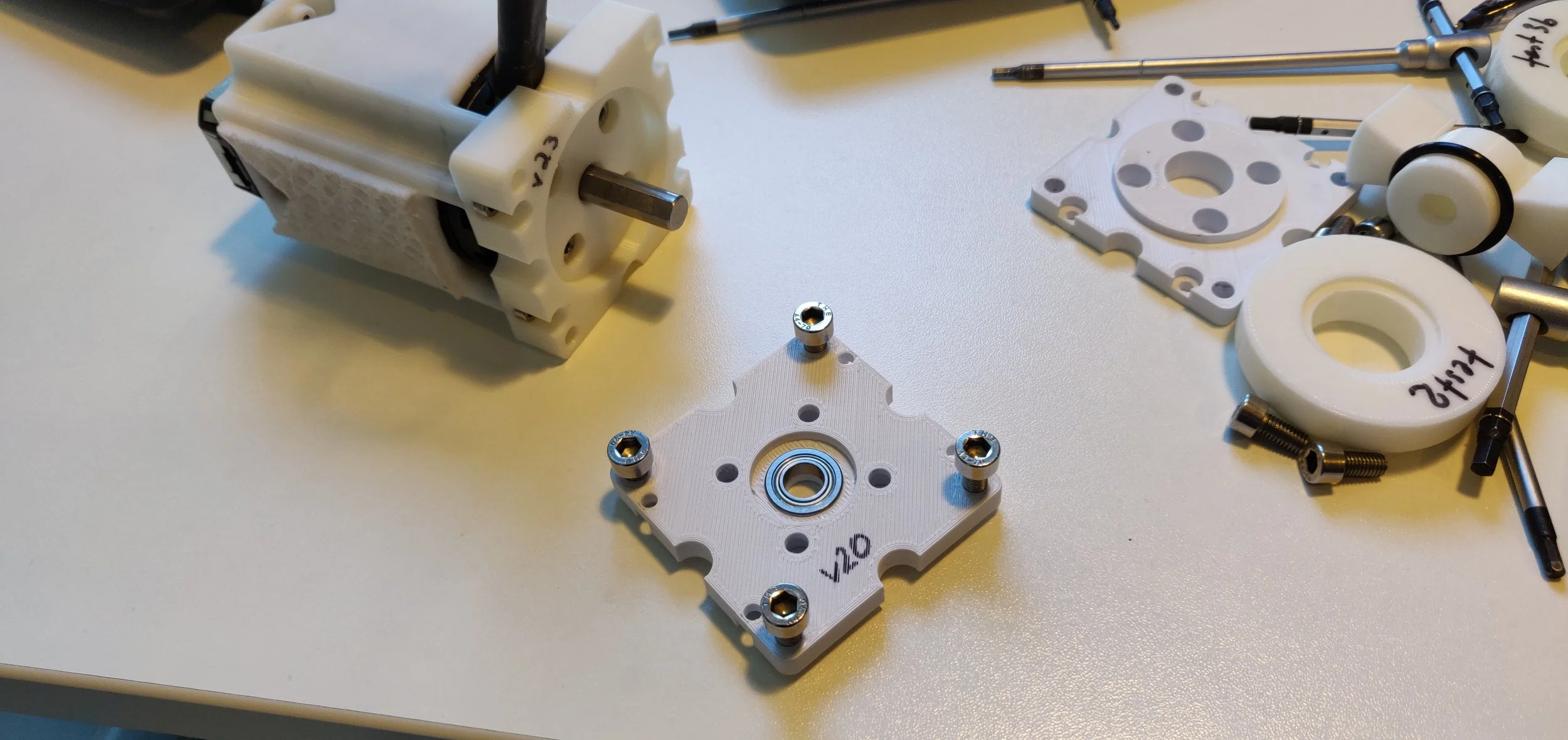
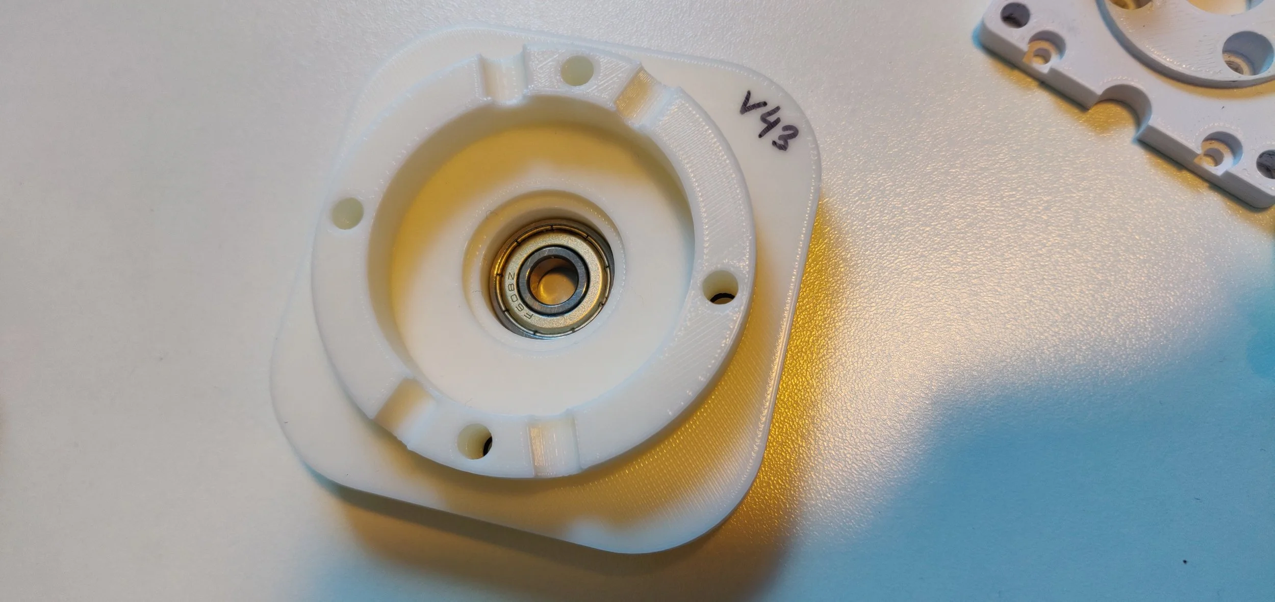
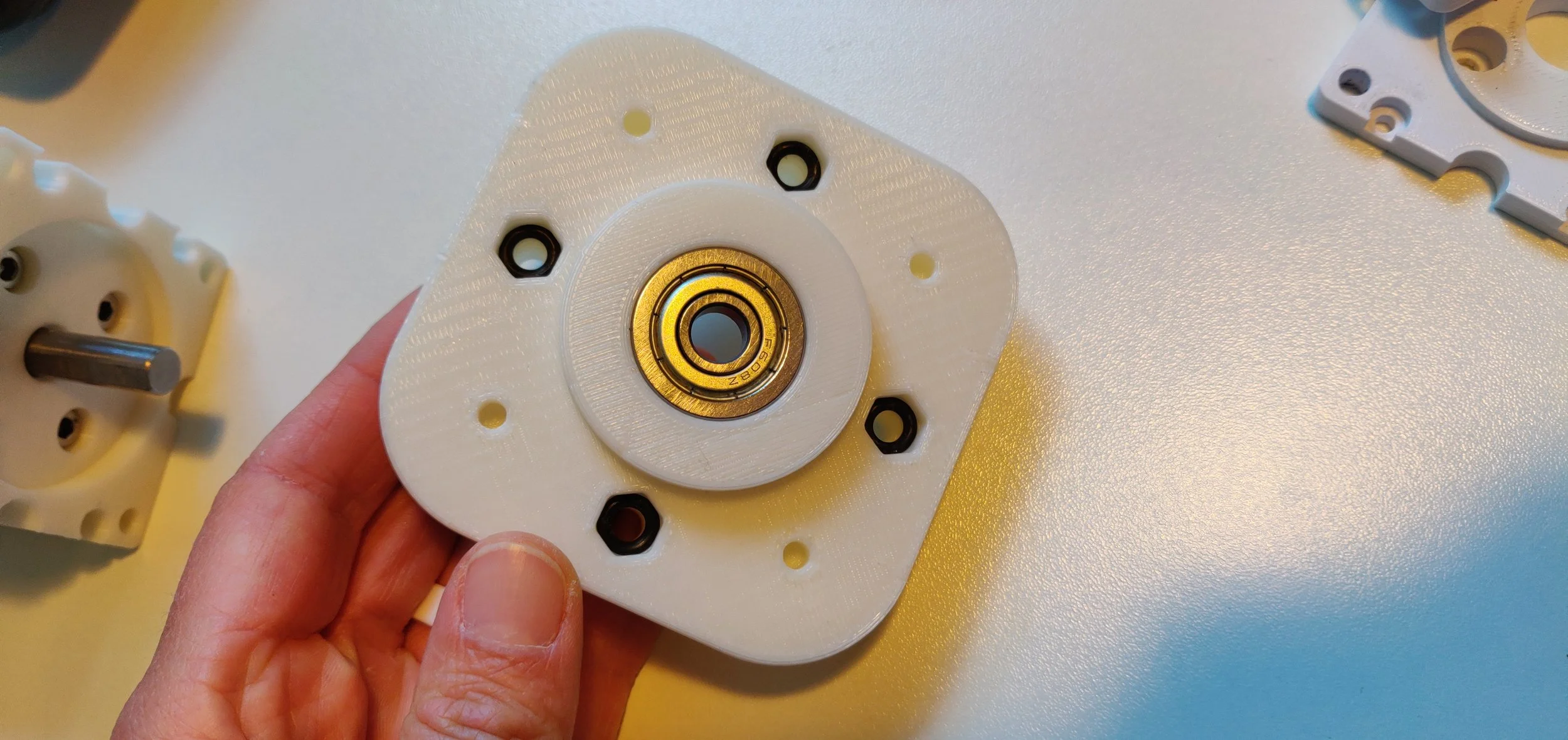
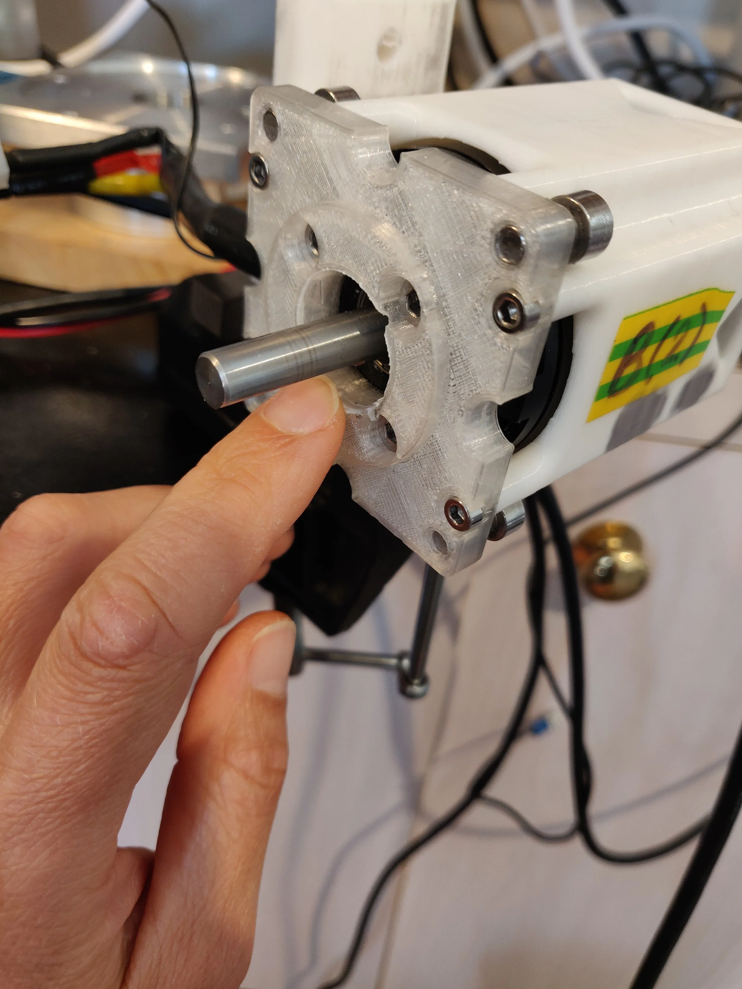
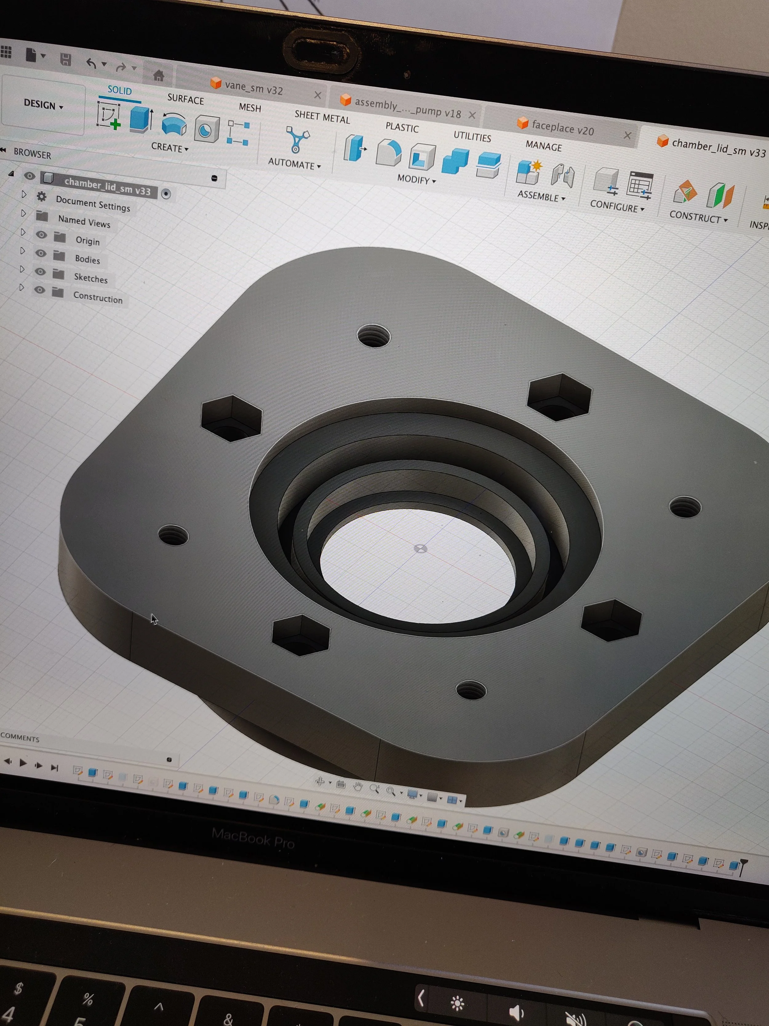
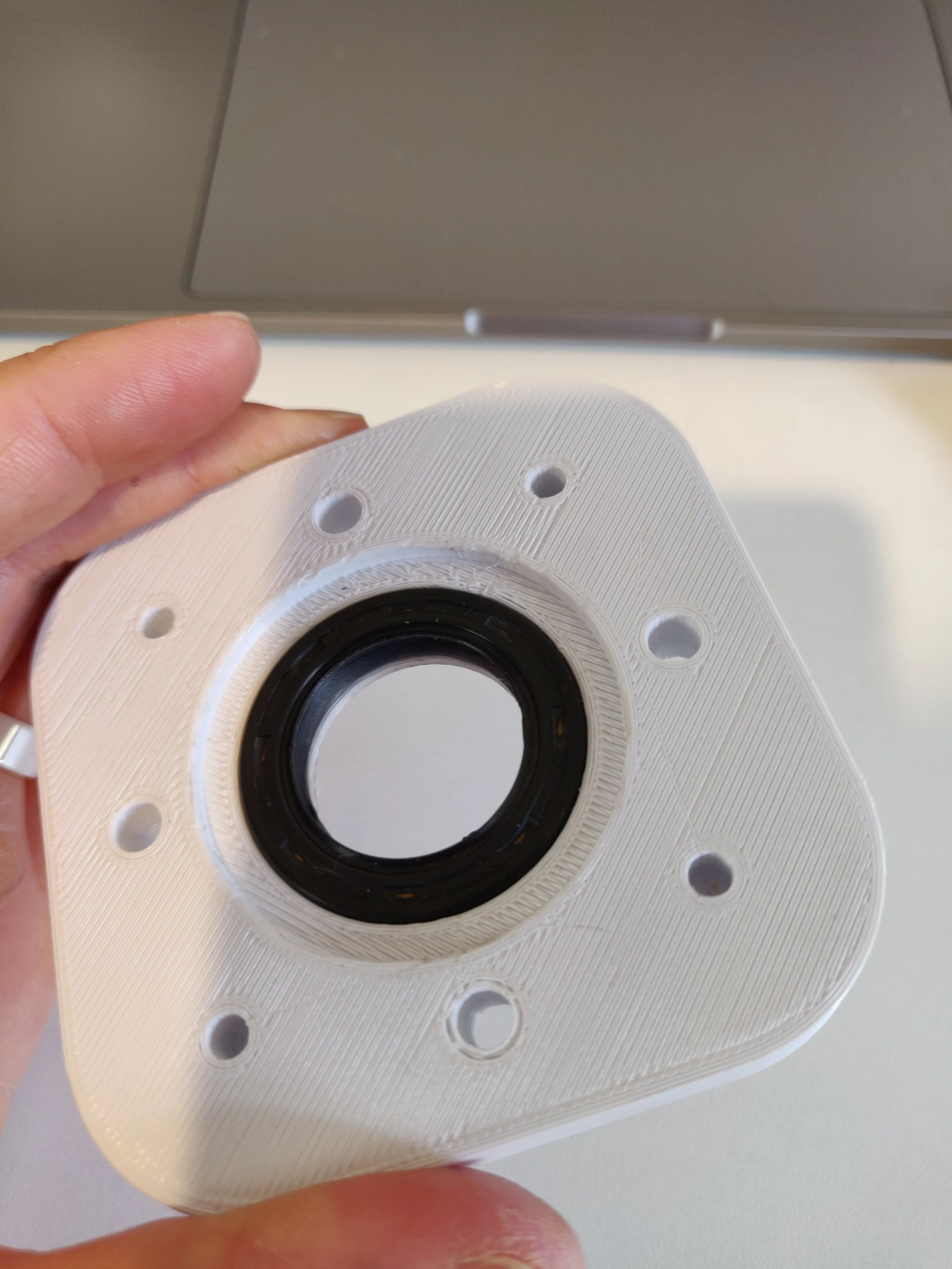
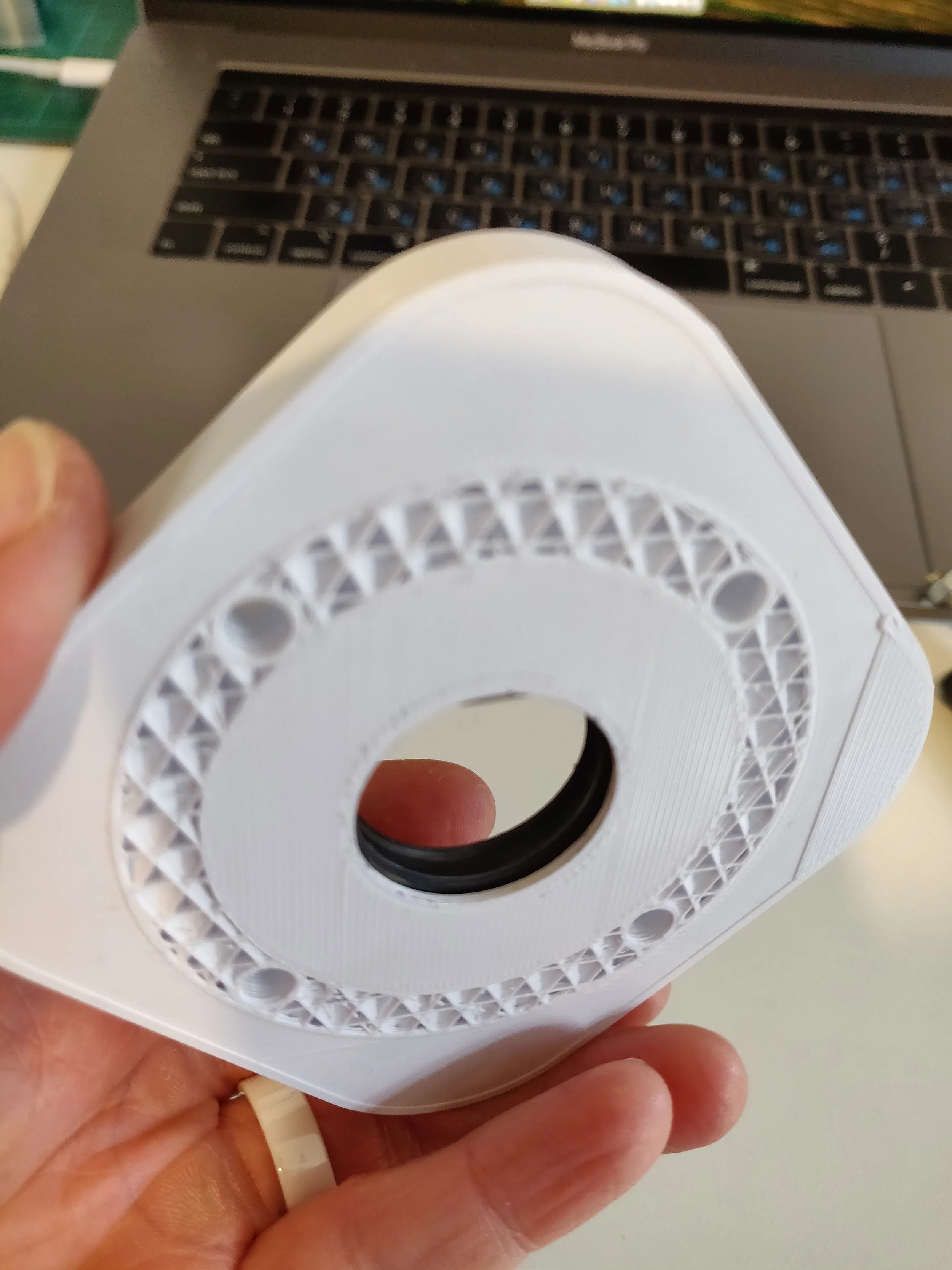
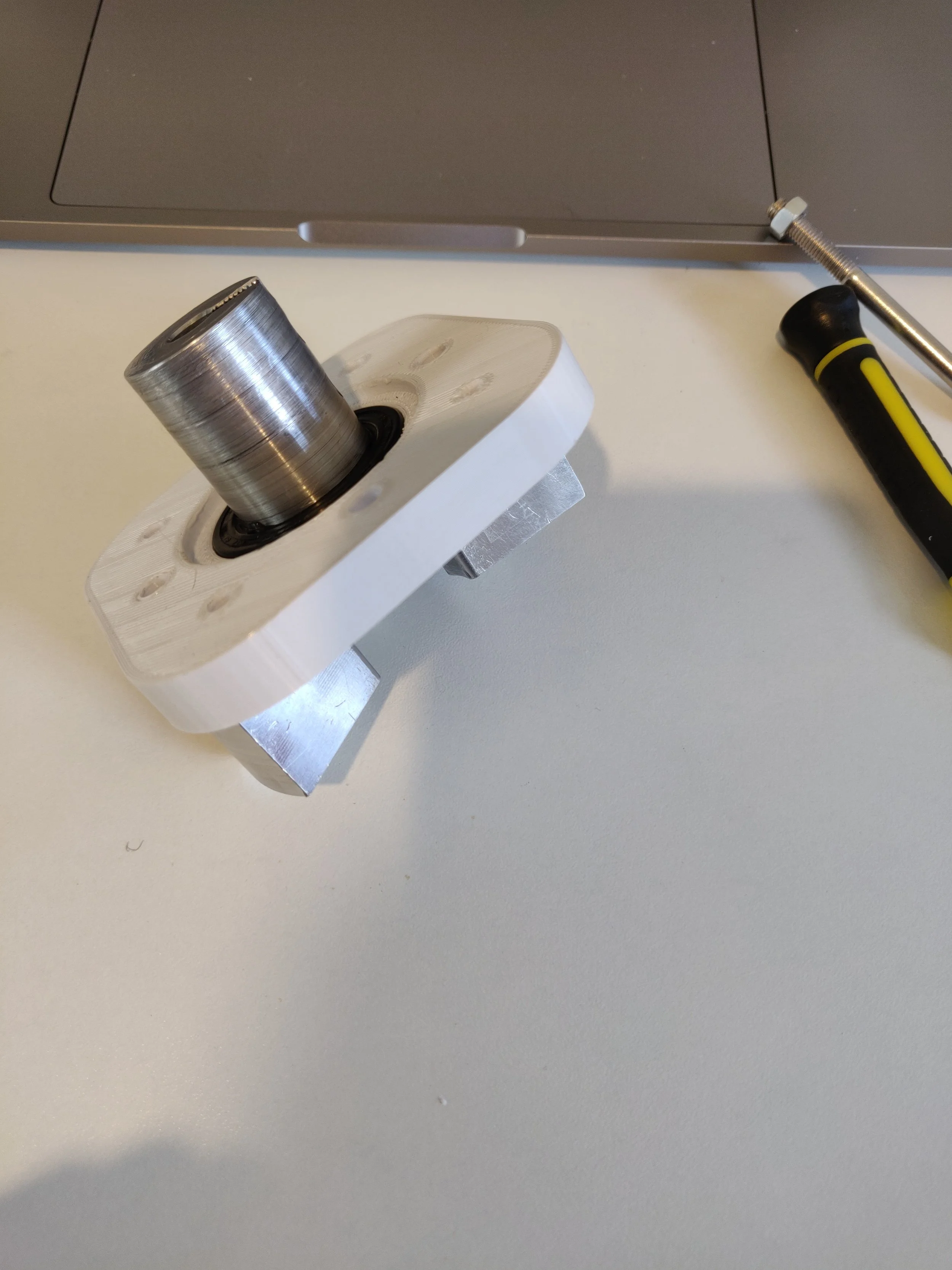
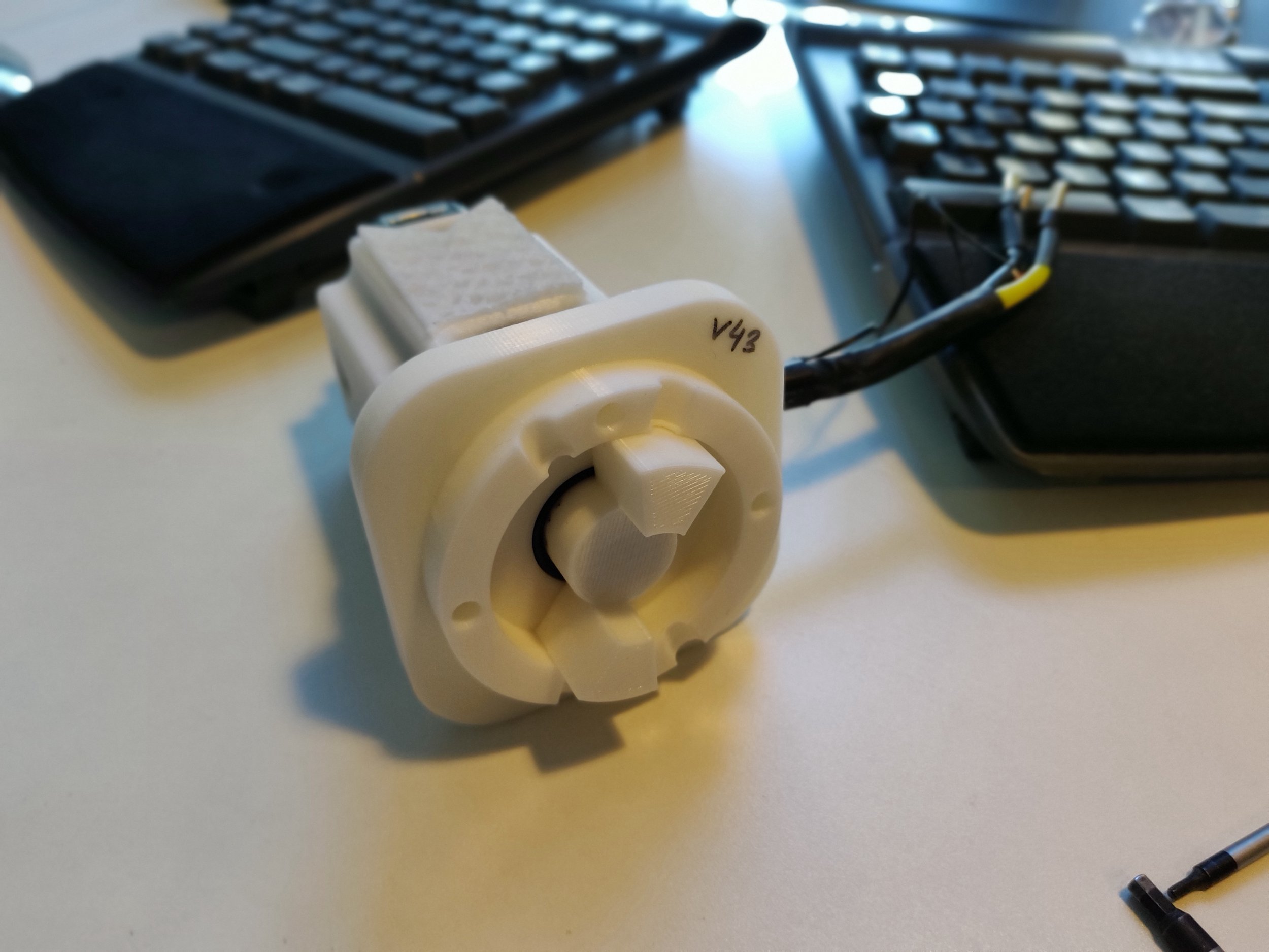
After disassembling the pump, we noticed some water pooling at the bottom of the motor faceplate (see figure 1 on the right). This is not good. We do not want water ingress into the motor area. At the moment, if you had a look at our assembly file, we have absolutely no provision for seals of any kind. This has to change. Now, bearings aren’t exactly seals, but for a prototype, it is probably not a completely braindead idea to insert them into the faceplate to at least provide a first-order obstruction for the passage of water into the motor. Figure 2 on the far right shows the updated faceplace with bearing.
Changing the faceplate to accomodate a press-fit bearing necessitates a shortening of the vane by exactly the amount that the vane protrudes past the chamber (i.e. 2.4mm). We have already understood that we can make the vane shaft shorter (and hence chamber thinner) but have not gone ahead with this change, as printing out a new chamber takes 8hrs. We will get to it.
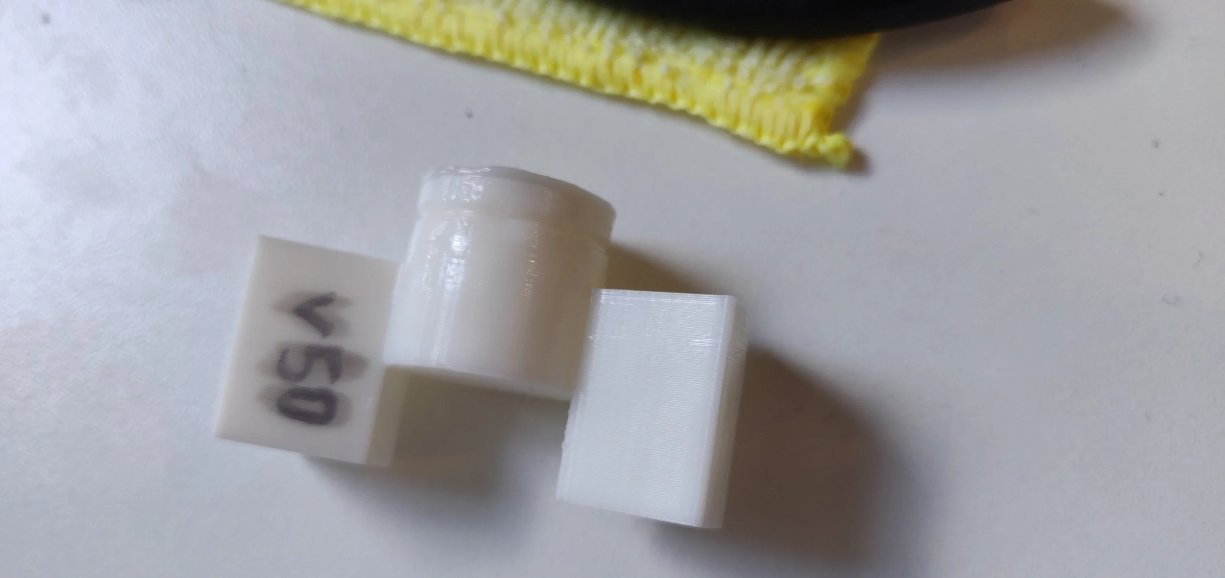
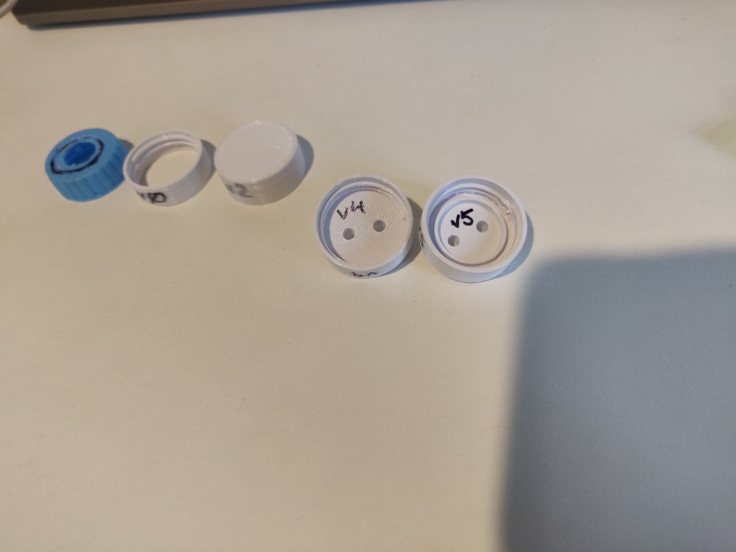
Now, onto the water provisioning tool. Figure 3 shows what it looked like as used in the video above. It did the job, but it is ugly. What to do? We make a bottle lid that has our required hose attachments. Turns out making a cap for a water bottle is not as easy as downloading it from Thingiverse. Figures 4 and 5 shows the progression of our bottle caps. The difference between v4 and v5 is the small circular tongue which stops water from leaking out of the 3D printed cap.
Figure 3 - original hose to bottle attachment.
Figure 11 - Motor with updated faceplate on the left side, notice the indent (deeper), with the previous (much thinner) faceplate in the center and top right, showing spigot originally sticking out of faceplate.
| Speed (turns/sec) | 0 | 1 | 2 | 5 | 10 | 15 |
|---|---|---|---|---|---|---|
| unloaded shaft, I [A] (min,max) | 0.000 (-0.003, 0.002) | 0.01 (-0.01, 0.05) | 0.02 (-0.02, 0.1) | 0.025 (-0.05, 0.125) | 0.05 (-0.05, 0.15) | 0.1 (-0.1, 0.3) |
| faceplate, I [A] (min,max) | 0.000 (-0.0015, 0.0005) | 0.01 (-0.01, 0.04) | 0.02 (-0.02, 0.1) | 0.025 (-0.05, 0.125) | 0.05 (-0.1, 0.15) | 0.1 (-0.2, 0.3) |
| faceplate, chamber, bearing, I [A] (min,max) | 0. (-0.002, 0.001) | 0.01 (-0.01, 0.04) | 0.02 (-0.02, 0.1) | 0.025 (-0.05, 0.125) | 0.05 (-0.1, 0.2) | 0.1 (-0.1, 0.3) |
| faceplate, chamber, bearing, vane (without o-ring), I [A] (min,max) | 0.0005 (-0.0015, 0.001) | 0.01 (-0.01, 0.04) | 0.02 (-0.02, 0.08) | 0.025 (-0.05, 0.125) | 0.05 (-0.05, 0.15) | 0.1 (-0.1, 0.25) |
| faceplate, chamber, bearing, vane (with o-ring), I [A] (min,max) | 0.001 (-0.001, 0.003) | 0.01 (-0.01, 0.05) | 0.02 (-0.02, 0.1) | 0.02 (-0.04, 0.1) | 0.05 (-0.05, 0.2) | 0.1 (-0.1, 0.3) |
| second motor, same assembly (as above), I [A] (min,max) | 0.001 (-0.00, 0.002) | 0.01 (-0.01, 0.04) | 0.02 (-0.02, 0.008) | 0.025 (-0.05, 0.15) | 0.05 (-0.1, 0.2) | 0.1 (-0.1, 0.3) |
| assembled chamber, 2 vanes, 2 o-rings, put bolts into place, I [A] (min,max) | 0.000 (-0.002, 0.005) | 0.01 (-0.01, 0.05) | 0.02 (-0.02, 0.1) | 0.025 (-0.025, 0.125) | 0.1 (-0.05, 0.25) | 0.1 (-0.1, 0.3) |
| assembled chamber, 2 vanes, 2 o-rings, motor, bolts tightened, I [A] (min,max) | 0.000 (-0.00015,0.0005) | 0.02 (-0.01, 0.06) | 0.04 (-0.02, 0.1) | 0.07 (-0.025, 0.15) | 0.15 (0.0, 0.25) | 0.2 (0, 0.5) |
Figure 15 - motor with faceplate.
Figure 4 - progression of bottle cap 3D printing prototyping.
Figures 12a and 12b - chamber inside and outside. Figure 12a - chamber inside shows the accomodation for an o-ring. Figure 12b - chamber outside shows the flanged bearing inserted, o-rings and hex holes for the M5 bolts that will hold two chamber parts together, deep spigot.
Figure 24 - cross-section of the current pump chamber design. Very likely over-indexed on o-rings.
Here we see the running of the Galin Pump (assembly of components, see here). Be kind. This is the first trial and I had a closed water bottle, hence, when water left the bottle, air entered, and you see annoying bubbles everywhere. The point of the video is to show directionally that the pump works with minimal leakage.
We have work to do.
Taking a look at the assembly file, there are many features that can be improved upon, some of these are:
add o-rings (grooves to insert them) to all bolts around the chamber,
add groove (and mating extrusion) around the chamber lids (180 degree groove, and 180 degree mating extrusion) should keep both chamber sides symmetrical (i.e. less unique part count). In the meantime, some glue will solve the problem :)
hexagonal nut depressions around chamber for easier assembly,
bolts that secure two sides of chamber need to be a bit further apart, it’s annoying that cannot secure them once motors are attached.
Figure 1 - finger pointing to where we have had some water pooling.
Figure 5 - protrusion inside the bottle cap necessary to avoid water leakage.
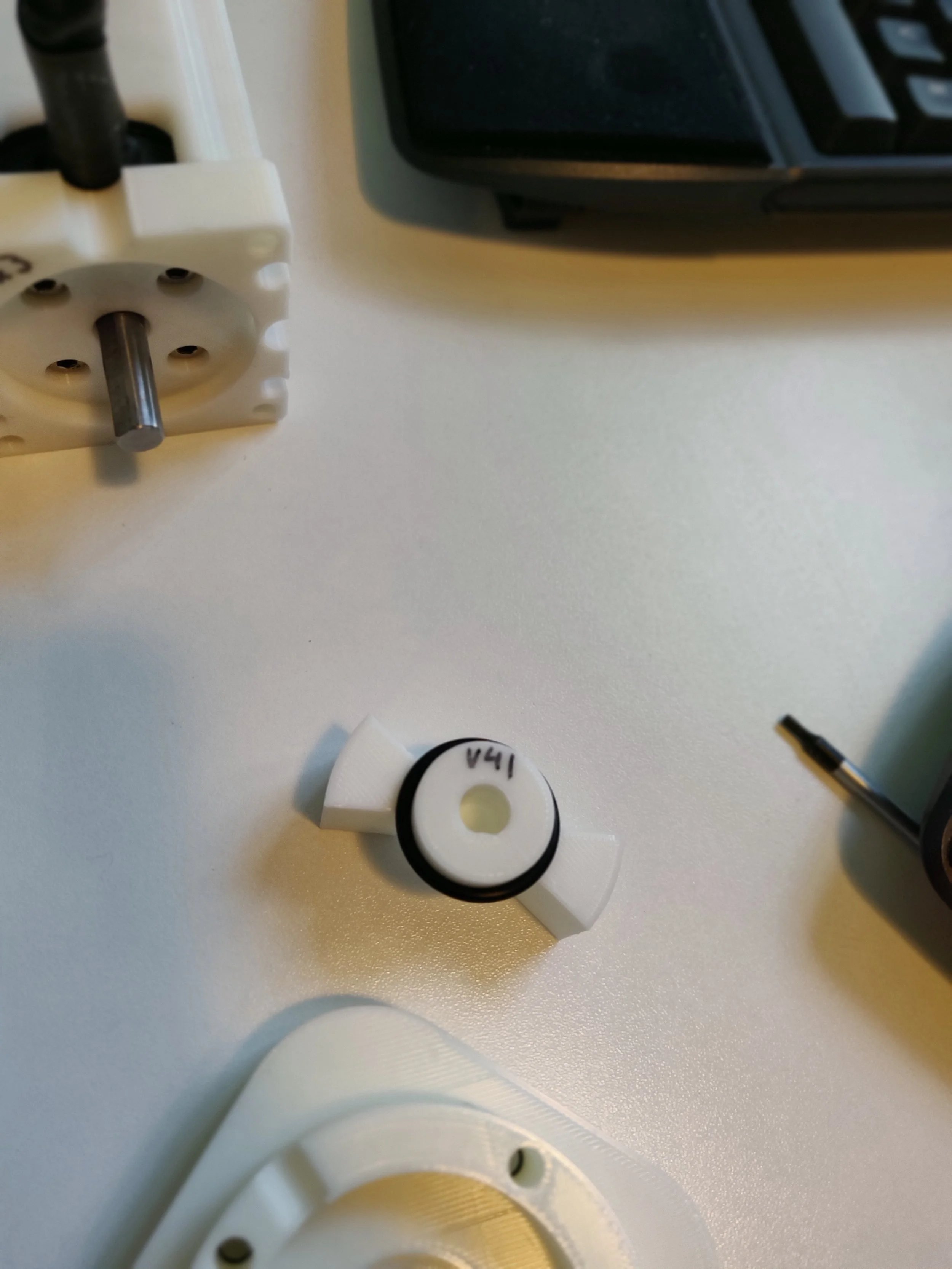
Figure 13 - the iddy-bitty little vane now with a 22mm shaft diameter to match the bearing, and with an o-ring.
Table 2 numbers allow us to draw a number of conclusions:
the increase in load from the bearing and o-rings is undetectable,
both motors behave similarly,
noticeable misalignment occurs when we attach both motors to the ends of the pump chamber.
It would be remiss of me not to mention that the results look so good, not because out-of-the-box the chamber, vane, o-ring assembly is so easy and seamless, but because from the very first measurement of current drawn by the unloaded shaft, I know what numbers to aim for. When I first insert the vane into the chamber, it does not spin smoothly - the chamber is not perfectly circular - however, after spinning at speed for some time, the vane and chamber wear into each other. Also, note that these numbers are not from a mathematical averaging of the current. These numbers are from yours truly eyeballing a plot of motor current as a function of time. As I mentioned earlier, these steps are just to get indicative numbers. What I want to know at this point, is whether I’ve really messed things up, not the precise friction increase from all components. An interesting side note, is that even though the bearings do not add much friction, they lead to a noticeable increase in audible noise of the motor spinning.
Assembling all these components has made it abundantly clear to me that the chamber will leak unless I provision an o-ring cord to go around the perimeter. It has also become clear (yes, it is obvious once you think about it…) that o-rings are static seals, not rotary seals (see figure 18 showing the wear and tear of an o-ring when used as a rotary seal) - I really should replace them with an oil-ring type seal. Finally, I am thinking of inserting a couple dowel pins along the perimeter of the chamber to help with alignment. Stay tuned for higher version numbers on the chamber component!
Below are some photos to help explain the rows in table 2.
Figure 17 - motor, faceplate, bearing, chamber, o-ring and vane.
Figure 18 - vane and o-ring showing signs of wear. O-rings are not rotary seals!
Interesting, running water through the above (figure 19) pump caused water ingress along the motor shaft, as well as through the M4 bolts that secured the motor to the faceplate. I haven’t seen this level of leakage with my previous very simple (no seals anywhere) assembly and so, I’m a bit stumped. One idea I have is that it is possible that the bolt holes through the chamber along the perimeter of the cylinder are conduits for water to the motor faceplate. I have completely redesigned the pump parts to remove these bolt holes, as well as adjusted various tolerances down a little to fit a bit tighter. Photos are coming once all the parts print.
In the mean time, what I am going to figure out is the water flow into the chamber through a 5mm diameter hole at some given pressure difference. I suspect this value will set the maximum speed at which the intake chamber can expand in order to completely fill with water, and similarly, the speed at which the same chamber needs to compress in order to push water out of the port.
Some brief back of the envelope calculations: if I hold a bottle of water about 1m above the pump, with a hose of 5mm (internal diameter) leading from the bottle into the pump, I would expect a flow rate of about: 87 mL/s out of the hose. I have a chamber whose maximum volume is: (95degrees) x 20 mm x ( 25^2 - 11^2) mm^2 => ~8.4 mL. Therefore, I would expect to fill this chamber volume in 96.5 ms. The leading vane travels 135 degrees during this time, and hence the maximum speed that it can travel to allow the chamber to be filled is: 135 / 96.5 / 360 => 3.9 turns per second (233 RPM for those of you that prefer these units). This is nice and modest.
I’ve been doing more testing over the last couple days to understand places of leakage. Moving the bolts that secure the faceplate to the cylindrical chamber outside the chamber, and inserting an o-ring around the perimeter of the chamber certainly helps remove leakage out of the chamber (compare figure 20 and figure 21). Further modifications to this setup would be to just glue the outside perimeter of the chamber - although internal leakage could still occur, and additionally inset the cylindrical chamber deeper into the chamber lid thereby providing more obstruction to water travelling out of the chamber, and maybe even adding an external o-ring?
Figure 21 - not leaky chamber lid.
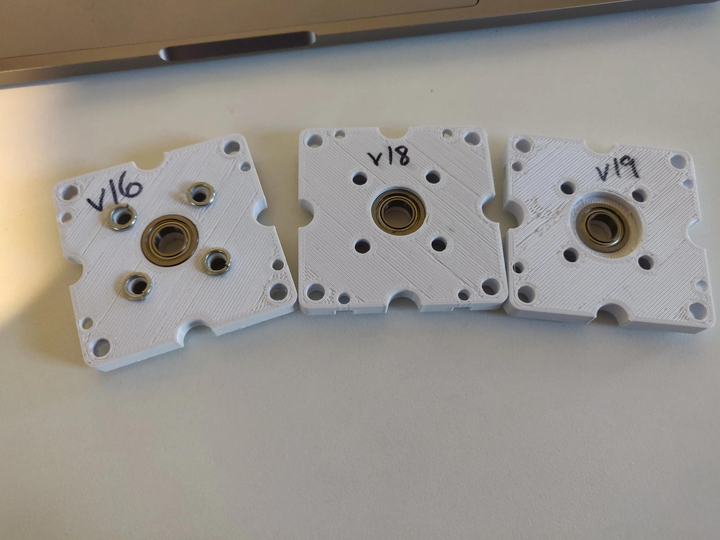
Figure 2 - motor faceplate updated to accomodate a press-fit bearing. The above version doesn’t actually work; it rubs against the motor case. Figure 6 with the progression of variants, with v19 finally being a working final (?) version.
Figure 6 - faceplate versions, mods necessary to avoid rubbing of motor casing against bearing.
Okay, so here we are - things are slowly coming together. But, we realised yesterday, that we can do a lot better in terms of sealing. What would work a lot better for sealing and centring the pump components to be coaxial with the motor shafts would be to:
increase the diameter of the spigot on the faceplate, and consequently mating insert on the chamber housing,
add an o-ring groove for the vane shaft on the outside of the chamber (todo, concerned with friction and tolerances in 3D printing) or, add an oil seal to the outside of the chamber (the conventional oil rings will not work when installed inside the chamber, as the groove of the oil seal connects all the chambers together),
and take this opportunity to decrease the thickness of the housing, as well as add hexagonal depressions on the outside of the house where hex nuts can go,
decrease the length of the vane shaft as well to neatly fit into the now thinner chamber.
…and here’s the result.
We’ve also increased the depth of the M5 threaded bolt holes in the chamber from 4mm to 6mm. The reason we did this, is that unfortunately, this particular thread has so far always just not been very strong, and we find it very difficult to secure the faceplate to the chamber. Maybe increasing the hole size will improve things - a little. At the same time, we’ve ordered a Helicoil M5 kit to attempt to get better threads in the plastic.
While we are waiting for the parts to arrive, it’s probably prudent of us to just test out the idea we have about how to insert an oil seal into the chamber housing. The CAD drawing is show in figure 7, with the 3D printed results in figure 8-12. It turned out okay, and most importantly the measurements I took of the thickness of the oil-seal lips, and depth of the groove were not too far off, as everything seemed to match up. We’ve got the faceplate printing right now, with the larger spigot to fit the chamber depression to verify further.
The one thing that bugs me is the lack of sealing between the chambers - we have not yet addressed this, except to say that this is something silicone glue can fix.
Here’s the result - showing that all the components fit well nicely, figure 11. Just waiting for NZPost to delivery the actual 20mm ID seals that suit our current design. While we wait we’ll experiment with some o-ring grooves, and gasket ideas to seal the two chamber lids.
Life
There’s no way around it - life just gets in the way of everything (i.e. lots of reasons and excuses for delays). Okay, never mind.
Here is where we are at today (Mon, 5th Feb). Made quite a few modifications to all the pump components, driven by various reasons:
oil rings arrived, but turned out to all be faulty (rubber film was not properly applied revealing the steel underneath) -> using simple o-rings instead, until I get a good reason not to,
want to keep chamber thickness as minimal as possible, but need space to absorb the 30mm of motor shaft -> inverted the spigot, now spigot protrudes from motor faceplate into the chamber,
shortened vane to minimal distance,
added flanged bearing to the end spigot.
Figures 11, 12, 13, and 14 show the various parts of the assembly.
and then life happens again. I’ve been very lucky until now not having to worry about PLA material going soggy, but alas, it finally happened. Baking the PLA as I write this, and thinking of further mods to the chamber, particularly around the perimeter.
Figure 7 - CAD drawing of the chamber lid, with the grooves, and tongue to accomodate the oil-seal.
Figure 8 - 3D printed result of the chamber with the 25mm ID, 37mm OD, 6mm thickness oil-seal inserted into place.
Figure 9 - another view of the chamber (we did not finish the print, so you cannot see the walls of the chamber.
Figure 10 - chamber and vane. The oil seal we had on hand had an internal diameter of 25mm, to fit our original 25mm shaft vanes.
Figure 14 - the assembly of motor, faceplate, bearing, chamber half, o-ring, and vane.
While we wait for the PLA to dry out, and then print a second instance of the three parts, let us figure out how much friction we have added with the bearing and o-ring. To do this, we look at the current drawn by the phases when the motor is spinning at a commanded speed as a proxy for the friction experienced by the shaft. Below is a table with some numbers from an earlier experiment:
| Speed (turns/sec) | 0 | 1 | 2 | 5 | 10 | 15 |
|---|---|---|---|---|---|---|
| unloaded shaft, faceplate only, I_ave (min,max) [A] | 0.001 | 0.01 (-0.01, 0.04) | 0.02 (-0.02, 0.08) | 0.04 (-0.06, 0.1) | 0.05 (-0.05, 0.15) | 0.1 (-0.1, 0.2) |
| faceplate, chamber and vane, I_ave (min,max) [A] | 0.001 (-0.002, 0.004) | 0.01 (-0.01, 0.04) | 0.02 (-0.02, 0.08) | 0.04 (-0.04, 0.1) | 0.05 (-0.05, 0.15) | 0.1 (-0.1, 0.25) |
| other side chamber and vane, I_ave (min,max) [A] | 0.002 (-0.002, 0.006) | 0.02 (-0.01, 0.06) | 0.04 (-0.02, 0.1) | 0.075 (-0.025, 0.15) | 0.15 (-0.05, 0.25) | 0.15 (-0.1,0.3) |
| motor attached to other chamber and vane, I_ave (min,max) [A] | 0.003 (-0.001, 0.006) | 0.03 (0, 0.1) | 0.04 (-0.02, 0.12) | 0.075 (-0.025, 0.175) | 0.15 (-0.0, 0.35) | 0.25 (-0, 0.5) |
What the above table shows us is the relative increase in friction as seen by one of the motors, as we assemble the pump chamber.
So, how do things look for our updated faceplate, chamber and vanes? Below are the numbers:
Figure 16 - motor, faceplate, bearing and chamber part.
Figure 20 - leaky chamber lid.
Figure 27 - deformation of the vane shaft after spinning inside an oil-ring.
Figure 23 - arrow showing the place where leakage is now occuring.
I assembled the pump with chamber lids as in figure 21. Figure 22 shows the assembled pump. Then, proved to myself that leakage was no longer occurring out of the chamber perimeter. However, there was a waterfall of water out around the vane shaft (see figure 23)! Water that will eventually end up inside the motor housing, and cause me endless grief. The bearing is absolutely useless as a stopper for water ingress (you mechanical engineers already knew this). Remember, earlier I wrote that I would go back to the oil ring idea only if I had good reason to? Well, looks like I just found my good reason. So, back to the drawing board.
One niggling reason that I have shied away from an oil-ring setup is that I had thought that the friction between the rubber oil-ring and PLA shaft would be high, and cause heating and wear and tear problems. Recently it occurred to me to add a bushing sleeve to the shaft of the vane so that the contact material between the oil-ring and shaft is bronze. I have some bushings ordered, and will test this out asap. In the mean time, I’ll just run along with what I have.
Figure 24 shows a cross-section of the now overly complicated set of parts that make up the new pump. In my desperation to avoid leakage I have swung the other way in complexity. There are likely to be many needless things that can be removed. But in the mean time, let’s print it, and see how we do.
Figure 26 - one half of the pump chamber assembled as per the design show in figure 24. Demonstration video of water being held in one chamber and not passing through to the other chamber (also did not pass onto the motor shaft).
Some good news, and some bad. The new version of the pump chamber with the plethora of sealing accomodations does in fact hold water without leakage pretty well. See figures 25 and 26 above. Figure 25 shows the 3D printed version of the design of figure 24 (but without the bushings - we are still waiting for these to arrive). The video in figure 26 shows water being held to one chamber, and not leaking into another (my finger is going purple as I apply pressure to keep the o-ring around the chamber flattened). The bad news is that my concerns about the wear and heating of the vane shaft if it were to spin inside the oil-ring bore out. Figure 27 shows the deformed vane after some test runs spinning at a constant speed. But that shouldn’t hold us back too much because the bushings have arrived and fitted.
Bushings arrived, and fitted, and water tests conducted. It was curious that water ingress along the shaft (into the motor) occurred on only one side (axis1 as I call it). Upon disassembly, I noticed that the rubber of the oil-ring on that side was ripped. Big question: how did this occur? Is it a fluke? Which side fluked? The other side (axis0) looks nice and clean, without noticeable water ingress. Compare figures 28a and 28b which show axis1 chamber and motor faceplate with water evidently present, to figures 29a and 29b, which show axis0 chamber and motor faceplate which do not have visible water present.
Long list of improvements:
I have a lot of improvements that I constantly think up, and then at some point either implement, or realise are batty ideas. I’m going to keep this list here (instead of the little post-it-notes that I tend to cover my working space with, and consequently annoy me, and ultimately get lost).
Future design ideas:
Had an idea that could glue bushing to vane shaft, and hence cause it to rotate together with the vane inside the oil-ring. But, after some thought, realised that bushings are not made to rotate, they are intended to have the shafts inside them smoothly rotate….but could still give it a go. [Doesn’t work.]
Another though, to do with sealing between the chambers, and reducing spinning friction: at the moment the surface area of a vane in contact with the chamber is quite large. This area is necessary for sealing off the port holes, however it contributes to friction when the vane spins inside the chamber, and there is leakage from one chamber to the next along this surface. If I were to put an oring around the perimeter of the vane in order to achieve a better seal, it would remove the effectiveness of the area for sealing the port holes, and effectively turn the vane from a wedge into a stick, so I may as well just have the vane be a stick instead of a wedge. This would increase the maximum volume, but decrease the minimum volume capable of being pushed out, so no, that won’t work.
To improve the sliding friction of the vane wedge along the inside of the chamber, I could cover (inspired by bushings) the wide side of the wedge with copper (ultimately, this will all be metal - this is just acrobatics due to the 3D printing prototyping).
Adding multiple sites for o-ring cord along the vane wedge wide side could improve the sealing - this won’t work well in conjunction with the copper plate idea, unless I’m very crafty, and manage to cut out thin strips of copper, and embed it perfectly between the o-ring cord sites.
Could I add copper plate cover along the side of the vane that is in contact with the flat side of the chamber? Am I just making a metal version of the pump?
It is pretty difficult to prevent water ingress between the chambers at the point of contact between the vanes (where they mate). To minimise this, maybe it is worthwhile to break the symmetry of the vanes, and have one side mate into the other e.g. a cone on one vane, mating with the reciprocal cone hole on the other vane? Again, this adds to friction.
Another solution to the vane mating/friction/leakage problem, is to have one vane fit inside the other, and a (you guessed it) metal bushings inside one, and outside the other - this makes more sense if I draw it. Additionally, what I don’t like about either of these ideas is the fact that it breaks the symmetry of the vanes. The two vanes are no longer identical. This has repercussions for manufacturing - the fewer unique components I have the better. But, at the same this, this is also possibly just an artefact of me using 3D printing for prototype design, so I should not be too wary of this.
There is absolutely no need to have the vanes be the wedge shape that they are - this is just the first shape that came to mind. It may be advantageous (for securing various sealing attachments) is to have the cylinder instead be a torus shape on the external face, and consequently, the vane be convex to mate with it.
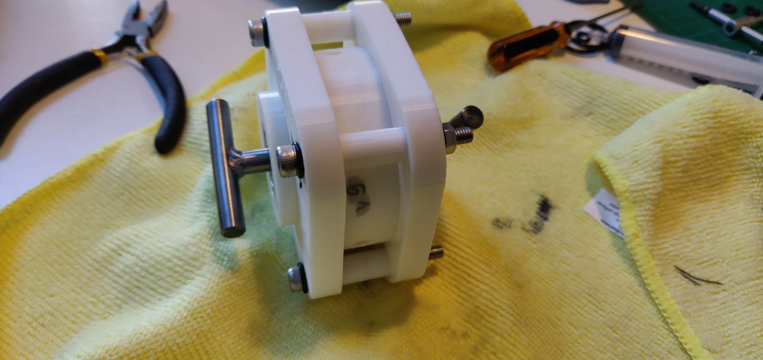
Figure 19 - complete pump assembly. Should I start considering changing the motors? These are looking really bulky. (Ultimately, motors choice will be dictated by pressure, and hence torque requirements. In my case it is dictated by access and convenience.)
Figure 22 - assembly of non leaky chamber lid version of pump.
Figure 25 - 3D printed version of figure 24.
Figures 28a and 28b - axis0 side of the pump, with no water ingress.
From the graphs we are interested in determining the maximum and minimum values of \(t_0\).
In GraphI, \(t_0\) is limited by the maximum acceleration that we have been calculating above, and using this value we can find that the minimum value of \(t_0\) is:
$$ (140^{\circ} = \frac{1}{2}a_{max}t^2_0)$$ $$t_{0(min)} = \sqrt{\frac{2\cdot140^{\circ}}{a}}=20.6 [ms]$$ (when \(a_{max} = 11570 rad/s^2\))).
In GraphII, \(t_0\) is limited by the maximum speed that can be used to travel \(40^{\circ}\):
$$40^{\circ} = v_{max}\cdot t_0,$$
$$140^{\circ} = v_{max}\cdot t_0 + \frac{1}{2}a\cdot t^2_0,$$
$$t_0 = 17.4 [ms]$$ (when \(a_{max} = 11570 rad/s^2\)), and \(v_{max} = 40 rad / s\) (~382 RPM).
Given the dimensions of the chamber (above) we known that 18 mL of water is injected&ejected from the pump every \(t_0\) seconds, therefore the maximum flow rate (at minimum \(t_0\)) is: \(Q{max} = \frac{18 mL}{t_0} = 1.03 [L/sec]\). How does this compare to existing pumps?
But…wait before we proceed, let us just confirm that the flow rates we are talking about are achievable by answering the question of what is the flow rate out of a 16 mm diameter hole out of a tank 200 mm diameter, and having water at a height of 200 mm, in the case that the shafts are moving at a constant speed relative to each other (not creating negative pressure between themselves). From Bernoulli’s principle, we get that this maximum flow rate will be about 9 L/s. Good, that’s a safe distance away from our desired flow rate of ~1.0 L/s calculated above.
We should note, that if we want to adjust the dosing volume of the pump - we could do so by adjusting how far the chamber expands from 0 degrees (to maximum of 100 degrees in our example above). This complicates the trajectory of motion of the shafts slightly. Practically, the regulation of flow is limited by the base speed of the pump, and measurable angle that the chamber can be made to expand by.
The manner in which we present the above pump speed, torque and flow calculations, may give the impression that the flow of the pump is a function of the head (water pressure) and thereby it is not in fact act like a positive displacement pump. However, a piston pump (definitely considered a positive displacement pump) could also be thought of as having the output flow dependent on the water head - and this is obviously the case for a practical pump in which the connected motor has a maximum output torque. Here is a statement for example that sounds confusing given our context: “A Positive Displacement Pumps is a "constant flow machine"“ I suspect that the reason this statement is made is because in the calculation of flow for the mechanical side of the pump (neglecting the device that will provide the rotary motion, and torque) the head of the liquid does not feature, whereas this is not the case for the centrifugal pump. At the end of the day, one can always fit a beefier motor to rotate the pump - right? I guess so. I wonder though, what would a performance curve look like for a piston+motor pump, and Galin pump when we consider the same electrical machines fitted to similarly sized chambers?
A colleague made the following observation to me that a positive displacement pump is analogous to a current source, and a centrifugal pump is like a voltage source. I like this comparison. But what I think this statement also highlights is that people seem to have forgotten that just like ideal current and voltage sources do not in fact exist, ideal positive displacement pumps, and centrifugal pumps also do not exist. Just like, in practice, a current source is limited by its internal resistance, and compliance voltage, the practical positive displacement pump is limited by the speed and torque output of the electrical machine connected to it (or by the speed and torque output of the rotating machine connected to it, if we want to stay generic).
Another thing that we should calculate/consider, once we have a working chamber is what is the maximum relative speed of shafts that causes an increase in the chamber volume (say from 0 degrees to maximum of 100 degrees) but that avoids cavitation (i.e. forcing in of air through seal integrity failures). We could probably model this, but should just find it experimentally.
If you have made it this far - thank you, you’ve learnt a lot about Galin Pump. This page is too long, and I will not add to it anymore, instead, because I have outsourced the pump mechanical design, I have split pump development into two pages:
Figure 29a and 29b - axis1 side of the pump, showing water ingress. This side has a broken/ripped rubber in the oil-ring.
Thur, 22nd Feb:
Yesterday I used Loctite to glue the bushing to the vane shaft. I did this so that the bushing would rotate and rub against the oil-ring, rather than the PLA material spinning inside the bushing.
Today, I compared the performance of the two arrangements. Axis0 has the original vane shaft (PLA) spinning inside a bushing, which is sitting inside an oil-ring. Axis1 has the vane shaft glued to a bushing and this part is spinning inside an oil-ring . Some observations:
axis1 was initially much stiffer, and difficult for the motor to rotate, however after a break-in period, the current drawn became comparable to the axis0 setup,
axis0 is very easy to spin for the motor, but it is much noisier when it rotates. As axis0 rotates black gunk begins to cover the vane shaft (that is probably carbon/graphite from inside the bushing wicking up the shaft),
comparing the position values from the encoders between axis0 and axis1, I do not visually (just eyeballing the graph) see a difference in the smoothness of rotation,
the current drawn at various speed values is the same for both axes, but it takes some time (in the order of 10 seconds) for axis1 to reach the same value as axis0,
the average current magnitude, as well as the min/max values are comparable with numbers given in table 2 (above).
I like the idea of the bushing spinning inside the oil ring, so I have just glued another bushing to a vane, and tomorrow, both side will be identical.
…Well, well…well… - thank goodness for my sometimes unwanted, but nevertheless followed through diligence. I took apart the two chambers and vanes, and realised that in axis1, the vane and bushing had in fact unglued. That probably accounts for the observation that I made earlier of the current draw decreasing in axis1. So, afterall, gluing the two components does not really work - at least not with the type of glue I have. Now that this has happened, it does make me think about how silly it may be to try to attempt to glue something to the inside of a carbon/graphite/oil imbued bushing. As for the noise: I’m running the motors without the chamber lids or vanes attached, and axis0 is still noisier than axis1 - I am starting to suspect the encoder.
Replaced the bushing in axis1, as inner carbon film had been damaged during the gluing/un-gluing process. Conducted some water ingress tests where I added water onto the chamber lid, and moved the vane around with my fingers, there is no visible ingress via the bushing/oil-ring channels into the other side of the chamber lid for either axis0 or axis1.
Mon, 8th April:
It has been a while. The current update is that I have hired an engineering firm to make the pump chamber. (For more updates on the pump chamber design go here, and for development of the control algorithm go here.) The situation was that I was making common mistakes that professional mech. engineers would (I hope not) make. I am not right now in the business of teaching myself mech. eng. (as much as I actually enjoy it) but in the business of making a pump prototype that showcases the various outstanding features of Galin pump. The fastest way to this goal is to leverage other peoples relevant expertise. In the mean time I can concentrate on the vane motion algorithm, as well as do flow calculations. Some of these that I have done already are below.
Once I receive the pump chamber, I shall connect an electrical machine (D5065) to each shaft. The pump will sit on my desk, and I will connect the inlet of the pump via two 16 mm (internal diameter - ID) PVC pipes to a water reservoir which also sits on my desk. Two outlet pipes (also 16 mm ID) will connect to another water reservoir about 1 m above my desk. Given the approximate dimensions of the pump chamber, the motor spec, and the pump setup I have just described, we need to calculate the range of possible speeds of the vanes, torques experienced by the shafts, flow rates, and other relevant parameters. Here goes.
Pump chamber dimensions:
outer diameter (\(R\)) : 50 mm
inner diameter (\(r\)) : 20 mm
height (\(d\)): 20 mm
vane angle (\(\theta\)): 40 degrees
density of water (\(\rho\)): 1000 kg m^-3
We need to get to an approximation of the maximum acceleration that the motor is able to develop. To do this we need to calculate the MoI (Moment of Inertia) that the motor sees. The MoI of the motor shaft is: \(MoI_{em}\) = 9.26 x 10e-5 kg m^2 (here). The MoI of water when the chambers are filled to their maximum capacity (i.e. the remaining 200 degrees) of the chamber is filled with water is:
$$MoI_{water} = \rho \cdot d \cdot \pi \cdot \frac{200}{360}\cdot(R^4 - r^4) = 1.33 \times 10^{-5} [kg m^{-2}] $$
MoI of shaft (made of Delrin, \(\rho = 1420\) kg m^-3) with two vanes per shaft is:
$$MoI_{shaft} = 1.51 \times 10 ^ {-5} [kg m^{-2}] $$.
The maximum torque from EM (electrical machine) is 1.5 Nm (1.9 Nm actually, from ODrive spreadsheet, but we use a conservative number).
The torque acting on vanes due to pressure of water at a height of 1 m is:
$$T_{wp} = 2 \cdot F \cdot l = 2\cdot P \cdot A \cdot \frac{R+r}{2}=2\cdot \rho \cdot h \cdot g \cdot d \cdot (R-r)\frac{R+r}{2} [Nm] $$.
$$= 2 \cdot 1000 \cdot 1 \cdot 9.8 \cdot 20 \times 10^{-3} (25 \times 10^ {-3} - 10 \times 10^{-3})\cdot\frac{25x10^{-3}+10x10^{-3}}{2} = 0.10 [Nm].$$
The maximum acceleration achievable is then:
$$a_{max} = \frac{T_{max} - T_{wp}}{MoI_{em}+MoI_{water} + MoI_{shaft}} = 11570 [rad / s^2].$$
In the case that we want to pressurise water inside the outlet chamber as though the water was at a head of 10 m:
$$T_{wp} = 1.03 [Nm], $$
and the maximum acceleration possible would be:
$$a_{max} = \frac{1.5 - 1.03}{MoI_{tot}} = 3884 [rad / s^2].$$
Given that the shafts (call them shaft A and shaft B) need to move \(40^\circ\) +/- \(100^\circ\) , i.e. the position pattern of the shafts is:
shaft A: \(40^\circ\) —> \(180^\circ\) —>\(220^\circ\)—>\(0^\circ\)—>\(40^\circ\)—>…etc,
shaft B: \(0^\circ\) —> \(40^\circ\) —>\(180^\circ\)—>\(220^\circ\)—>\(0^\circ\)—>…etc.
The shafts’ trajectories lie between two extremes:

